
Stepped planing hull – pros and cons (Eng)
There are a lot of legends connected with steps on hulls.
Many people claim that this solution is good only for the racing industry and is very dangerous for normal recreational users.
What are the real facts, however? There is ample evidence showing that the stepped hull has less drag than the classic deep V-hull.
The real step forward in this field was made by Clement and Koelbel in 1992, with their dynaplane and traverse step and hydrofoil form.
A few years ago, in 2012, White and Breaver examined stepped and unstepped V-hulls during extensive tank trials. The research was conducted for the US Navy, and the point was to prove if the stepped hull can be a better alternative to the classic planning hull in terms of performance (economy) and sea keeping of fast boats.
The Navy had clearly indicated their needs, demanding that the angle of attack did not exceed 2.5 degrees! The 142 tank tests were done with different localization of LCG on a 53 feet prototype – 25% , 30% and 35% of LWL (46 feet), respectively, which was a good real life approach. The comparison of results was made with the following models: one unstepped, one transverse step and two transverse steps with variation of their height and localization.
Beforehand, in 2010, Savitsky and Mrabito had clearly confirmed that the wetted area varied inversely as an exponential power of trim angle. A good example of this dependence was depicted by Garland (2010 – Stepped Planing Hull Investigation), please see below:

Source: William R. Garland “Stepped Planing Hull Investigation” site 7 Figure 9
Going back to White and Breaver`s tests, it is now easier to understand what a difficult task the Navy had given them (performance at low trim). Quickly conducted tests have shown that the stepped hull has lower wetted area and less drag than the unstepped version of the hull. However, the running trim was higher than expected. According to the Navy, the best comfort for the crew and for sea keeping was achieved at the aforementioned 2.5 degree of tau (angle of attack). To fulfill this requirement, White and Breaver used trim tabs but, not surprisingly, this always led to a much higher R/W (drag/displacement) ratio: unrealistic 16 degrees of deflection were needed to reach the target close to 2.5 degrees.
In order to find a solution to this problem (more lift at stern), the scientists used the results of the research done by Rosse and Kruppa in 1991. They had proved that a lift close to 187% of thrust was generated by a surface piercing propeller with best P/D ratio at 1.1 and the shaft angle close to 8 degrees. Basing on these findings, White and Breaver went back to the tank trials and got very good results in terms of drag and the required tau (good sea keeping). The resistance drop was approx. 23% at 2.5 degree tau in the best configuration of steps and volumetric Froude non dimensional parameter[1] at 4. Even with the non-stepped deep – V hull the resistance drop with surface drive was about 13 %. This clearly indicates the advantage of the stepped hull especially with surface drive (not surprisingly all high speed racing boats work with this configuration) over the deep-V hull.
In 2010 W. Garland investigated one deep V-hull with one step. His tank trials showed that the best configuration in one step hull was at 4% of beam (high). The aforementioned R/W relationship shows that if the volumetric Froude number is close to 3, the difference between the well proved Savitsky`s prediction (1964) and the stepped hull starts to be visible. According to Savitsky`s prediction, the resistance sharply increases with speed from R/W = 0.15 at the mentioned Fn∆=3 to R/W=0.27 at Fn∆=5.4 while the drag of one stepped hull (VS=4%beam) increases much more slowly to R/W = 0.18 – see below
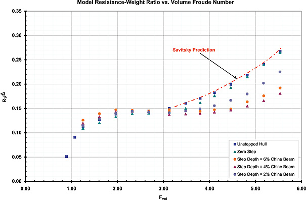
Source: William R. Garland “Stepped Planing Hull Investigation” site 8 Figure 11
Higher steps (6%b) result in lower wetted area than 4%b (and 2 % of beam respectively) but, due to a higher trim, develop a much higher wave making resistance. Higher steps need a compromise and in the case of Garland, one step 4% version of chine beam gives the lowest overall resistance (in his case it was 94.2% resistance of 6%b high step, 80.3% of 2%b and only 67.5% resistance of the unstepped version).
Problems connected with the stepped hull occur in the lower range of speed (Fn∆<2.6): due to the lack of fluid separation on steps, the hull generates higher resistance than the unstepped hull. This is an important factor that has to be taken into account while matching the right propulsion set. In the pre planing range, the thrust line should follow the resistance line with a safety margin for acceleration (min 20% according Blount and Bartee – 1996).
In 2014, Lee and Pavkov went further with instigation of the stepped hull – they were looking for the best configuration of two steps with variable height (unlike White and Breaver, who in each case had an equal height of steps). When it became apparent that the first step should be located just behind the centre of pressure, close to the centre of gravity, the investigation was based on seven different configurations of steps height. Lee and Pavkov`s work confirms that in each testing configuration the stepped hull has a lower drag than the unstepped one. They found the best results with the height of the forward step equal to 0.7%b and the aft step 2.1%b (beam): the R/W (resistance to weight) ratio from 0.17 to 0.19 at speed coefficient Cv[2] from 3.4 to 4.4, respectively.
Weight distribution was similar to the one in Clement and Koelbel`s work (forebody 90% afterbody 10%) – 82% for two first planing surfaces (for the aforementioned best configuration)
The origins of advantages of the stepped hull are in pressure distribution along the hull. A good example is shown in the work of Garland and Maki (2012), see below:

The well-known phenomenon of pick pressure[3] occurring near the stagnation line[4] is clearly visible on the above graph. The solid line represents the unstepped hull and the red and dotted ones the step hull with different localization of steps. As we can see, the one step hull has two pick pressure points (and three in the case of two steps) and in all cases, the sums of hydrodynamic lift connected with these points of max pressure are higher than in the unstepped version. The higher the lift, the lower the wetted area and viscosity resistance[5] . As it was mentioned, hull resistance is strictly dependent on the value of boat trim (tau – τ). The higher angle of attack (tau) is, the higher the wave making resistance and the lower the viscosity resistance. Thus, finding a reasonable balance between the needs of good sea keeping and performance is not easy. Basing on the aforementioned examples, a well-designed stepped hull – especially with a surface drive – is a tempting alternative to the classic unstepped hull.
In 2009, Savitsky and Morabito in their state-of-the-art study of wake behind the step have given input to mathematical modeling of parameters, which makes it possible to determine the performance prediction of the stepped hull.
For β > 10
HCL(xCL) = b1*0,17(2+0,03*(Lk1/b1)*τ^1,5)* sin((PI()/CV1)*(xCL/3b1)^1,5 )
and
H1/4(x1/4)= b1*0,17(0,75+0,03*(Lk1/b1)*τ^1,5)* sin((PI()/CV1)*(x1/4/3b1)^1,5 )
Where:
HCL – height of wake profile above extended keel, [m]
H1/4 – height of wake profile above extended ¼-beam buttock, [m]
b1 – beam of planning surface of forebody, [m]
CV1 – speed coefficient, forebody
Lk1 – wetted keel length, forebody, [m]
xCL – distance behind step where centre line wake profile intersects with aft hull keel, [m]
x1/4 – distance behind step where ¼-beam wake profile intersects with aft hull ¼-beam, [m]
Basing on these equations, in 2009 David Svahn described practical examples of drag calculation for the stepped hull and the eventually needed SHP (one step without input of additional lift by surface drive).
Building a fast performance power boat using the advantages of the stepped hull requires great experience and knowledge of the designer. First of all, one needs to consider the shape of the steps (there are three different models: simple transverse, re-entrant and pointed aft – each with different pros and cons), longitudinal localization (too short distance to aft step and the wake can miss the hull, another issue – stagnation line shouldn’t cross the first step, otherwise additional drag is created), localization of LCG (with wrong placing the stepped hull can be unstable –
solution: Morabito, Pavkov, Beaver 2014); then the height of the steps, and last but not least, the best performance and ride comfort especially on rough water.
Whenever you consider the stepped hull, always check who has designed the hull, ask about the performance prediction, and check the thrust margin at hump and top speed if displacement is realistic and how the trim in the range of speed and displacement behaves (comfort of ride). A good designer has plenty of solutions to improve the hull`s ability to meet client requirements and make it safe.
[1] Fn∆=Vs/(g*ᐁ^1/3)0.5 this is a better indicator of comparison than just speed, for example 8 tone speed boat has Fn∆ equal 5.8 at speed 50kn
[2] Another, frequently used non dimensional indicator of speed and beam equals CV=Vs/(g*b)0,5 ;for example 2.7m chine beam boat at 50kn has the CV=4.99
[3] Pmax/q= sin2α where q= ϱV2/2 and α=tan-1(π/2*tanτ/tanβ)
[4] Actually for deadrise hull the free stream not fully stagnate (only fort flat plate). With non- zero deadrise stagnation point is somewhere in spray rot region.
[5] Total hull resistance components: pressure resistance (wave making), viscosity resistance (wetted area), appendage resistance, whisker spray resistance and sea state resistance.
author: Jacek Pawlik
Podziel się: